Tadano Group

INNOVATION


SAFETY

Development of world-standard safe Mobile Elevating Work Platforms
  1. Introduction

    Mobile Elevating Work Platforms (MEWPs) have been introduced to work at heights safer and more productively and to reduce construction costs. Using MEWPs at these construction sites prevents accidents such as falls and reduces the work time to remove scaffolds. In addition, it is also beneficial for the workers, as it reduces fatigue from going up and down the working site.
    Since the benefits of using self-propelled MEWPs at work sites have been recognised, they are widely used in various sites and environments, from outside construction to civil works. This has increased the demand for the development of safer MEWPs.
    The required level of safety performance differs from country to country. For example, the European CE standard, which is said to be the most demanding in the world, requires a very high standard of safety functions.
    This time, Nagano Industry developed “hard-to-tip MEWPs ” that meet CE standards, and we will introduce our new safety features.

  2. Improving stability – prevent tip-over

    The framework of the stability criteria of the CE standard is shown in Figures 1 to 4.
    Figures 1 to 3 show the static stability assessment items. The evaluation is carried out with the machine stationary. Figure 4 shows the dynamic stability evaluation items. The assessment is carried out with the machine in motion.
    The first diagram shows the evaluation with wind force applied to the vertical projection of the lifting device. The system is checked not to tip over even under strong winds of 12.5 m/s.
    The second diagram represents the assessment of push-pull loads. It is evaluated by adding a pushing and pulling load of 200 N per person, per side, on the platform. (400 N for two persons).
    The third diagram represents the evaluation by considering the lifting device’s operating inertia force (0.1 G).
    The fourth diagram represents a test to travel over a 10 cm kerb. Again, ensure that no falls occur.
    The CE standard requires these four stability criteria.

    Fig. 1 No tip-over when
    the wind blows.
    Fig. 2 Operator push and
    pull loads.
    Fig. 3 Operating inertia of
    lifting devices.
    Fig. 4 Overcoming a 10 cm
    step.

    CE standards prohibit the simultaneous operation of lifting, lowering and turning while travelling. This is because the change in the machine’s centre of gravity is significant, making evaluation difficult. For this reason, the machine was designed not to raise/lower the boom or turn while in motion.
    In addition to meeting the safety requirements of CE standards, the allowable tilt increased from 3° to 5°.
    The reason is that application of MEWPs on slopes is anticipated to increase. Even on the such inclined ground, operators can work at height with feeling secure if the machine’s safety function is trusted enough, i.e. less chance of tipping over.
    In order not to reduce the working range by making an allowable tilt from 3 to 5°, the model NUL09-7 (Table 1, Fig. 8) has a larger body and increased machine weight. At the same time, the width of the body was reduced to less than 2000 mm to allow the machine to use the construction lift.
    See Figure 5. The tipping limit angle of the completed machine was significantly improved for the max outreach. Although this was tested with rated load capacity, the machine has less chance of tip-over even on inclined surfaces, which is approximately 2.7 times less than the previous models’ limit angle.
    In the control system, the reliability of the safety control has been significantly improved through dual angle sensors: high-precision tilt sensors and an avoidance control system for hazardous side movements in addition.

    Fig. 5 Comparison of performance
    Previous model NUL090-6
    New model NUL09-7
  3. Overload sensing

    The cause of many MEWPs tip-over is exceeded loading more than the rated capacity on the platform. As a result, workers often load exceed to minimise their work time.
    To minimise the risk of accidents, load sensors actively monitor the machine’s platform load, which reduces the operator’s guesswork.
    When the platform load exceeds the rated capacity, the sensor sounds an alarm, lights the alert lamp, and disables boom and travel functions.
    The alert sound and lamp stop and resume when the load is back within its rated load. (Standard function on models NUL 12-7 and above)

  4. Telematics system

    A telematics system can monitor the machine’s status remotely. It captures the machine’s location and engine operating status when installed using GPS and a telephone line. In the event of product loss, it can control the engine activation remotely. (Optional)

  5. Operator-friendly display panels

    (except for some models)
    The upper control panel is the only source of information on the machine’s status while the operator is working at height on the platform. The following new functions have been equipped.

    • Tilt level indicator

      The indicator shows the tilt level of the machine

    • Error code display

      Information on the malfunction is displayed with a three-digit error code. This provides a clear solution to the problem, quicker service response, and eliminates the anxiety of operators left on the platform.

    • Operation lever assist display

      If the tilt surpasses the allowable tilt, the sensor disables the boom and travel functions to prevent tip-over. In such cases, arrows on the control panel indicate the direction the machine should return to a safe position.

  6. Deadman device

    MEWPs are equipped with an emergency stop device. If the machine moves in a way the operator does not intend, the system cutouts the operation. However, the emergency stop function may not be operable if the operator panics due to unexpected circumstances. To ensure the operator’s safety in such cases, the control system continuously monitors the machine’s status and stops operation when it detects an abnormality.

  7. Summary

    Our newly developed machines offer advanced safety features and our trusted know-how and technologies from a long time as a manufacturer.
    We also offer workers maximised safety, efficiency and productivity at their work sites.

    Table 1 NUL09-7 Specifications
    Maximum work floor heigh mm 9,010
    Maximum outreach mm 6,480
    Maximum loading capacity kg 200
    Stowed position Length mm 5,250
    Width mm 1,980
    Height (without PAD) mm 2,250
    Machine weight (rubber crawler) kg 4,750
    Allowable tilt ° 5
    Dimensions Crawler centre mm 1,870
    Tambura-centric mm 1,680
    Average ground pressure kPa 41.2
    Fig. 7 NUL09-7 External view

ZERO-EMISSION

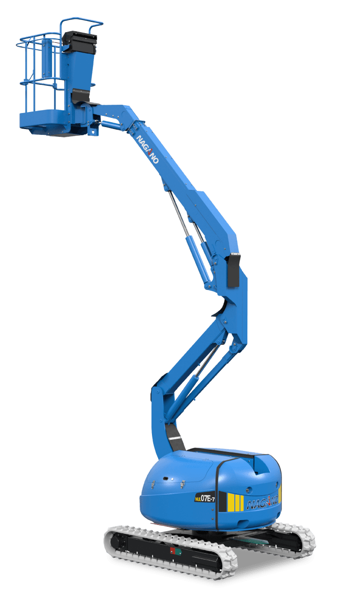
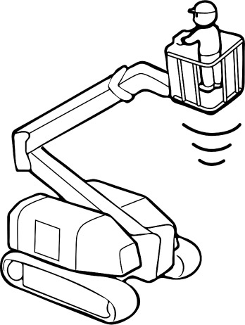
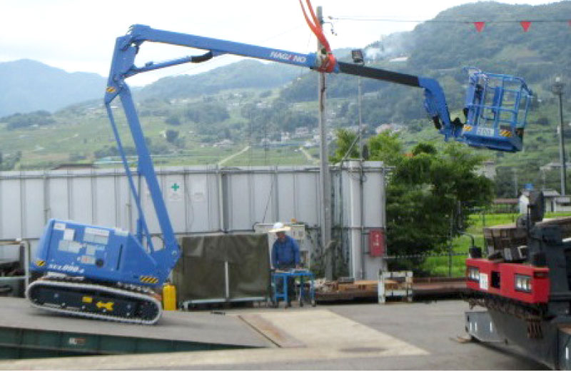
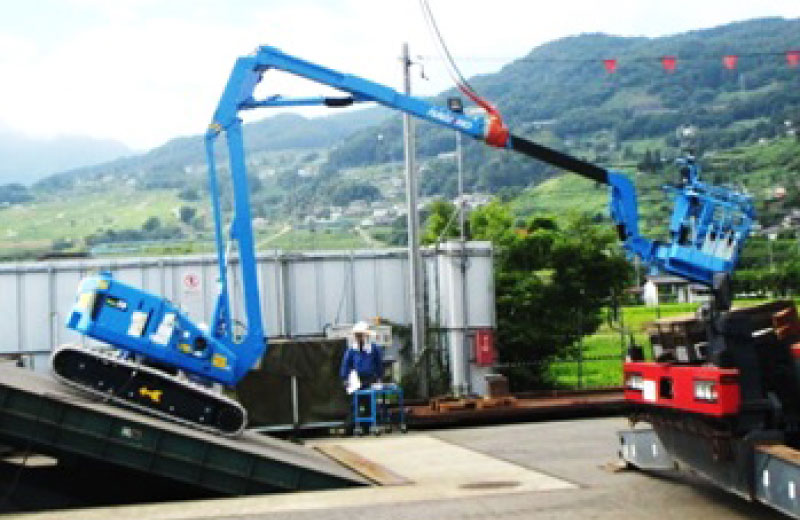
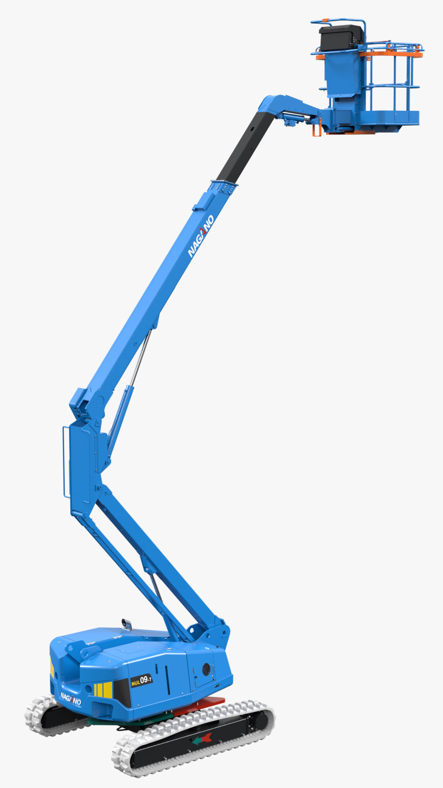
(Battery-powered crawler type 7 m articulated boom lift)

Our First Electric Access:
Crawler-type articulated boom lift

Product features
  • Work 8 hours during daytime => Full recharge overnight
    (Nagano standard operation pattern).
  • Equivalent operation and traveling to engine-powered machines.
  • Reduced noise, low vibration, low heat emissions ⇒ Ideal for work in urban areas, underground, tunneling and indoor.
In NAGANO standard operation pattern,
Capable of approx. 50 times motions
*assumed 15 times motions a day

3 working days on a single charge

Long battery life

Equipped with an AC motor and a high-capacity battery

Equipped with emergency descent function

The boom lowers manually in
battery problems

Standard battery

AGM Maintenance-free batteries


NEW STRUCTURE

Mechanism- control centre of gravity

The centre of gravity of the front attachment lift boom is combined with the centre of gravity shift of the telescopic boom and a special link structure is provided so that the centre of gravity is always on the stable side as the machine attitude changes. By optimising the current model weights to a leaner dimension, the overall weight of the machine is 1.8t less than that of its class, while maintaining the same level of omni-directional stability.